
Sunday, September 29, 2013
Thoughts on Model Railroading Part 2
Although the layout plan has been posted, this blurp will delve into the process it took to get there. When it came to a layout design for our club, many things had already been decided. The foot print of the layout was designed by Don Pearce, giving us wide aisles, an island branch line, and the ability to follow your train around the layout without having to jump from one side of a wall to another (see Don's Plan). We had also decided on a two percent grade, thirty inch radius curves, number six Atlas switches and ten foot plus passing sidings. The ability to turn full passenger trains at each end of the run was also high on the wish list. Some thought was given to modeling the line that use to run from Port Dover to Hickson, but most of the structures would have to be scratch built and it would limit the scope of the railroad eg. no logging branch or ore mine, both wanted inclusions. A double main line was another idea suggested by some members, hey great for running lots of trains. You still could add the second track to our layout with some modifications. If the main line was reconfigured so that every other town was either entirely on the right or left of the main line it could also be run as point to point with each track of the main being a single main line and only switch the sidings on that side, doubling the length of the main line. Put another way, starting at the lower loop a run would take you all the way to the upper loop which would now be the middle of the run and all the way back to the bottom loop. Well let's just say double the track, double the money, so that was dropped. So that is how we came to a folded over loop to loop design, with the loops on top of each other. There will be a staging yard off the bottom loop and a city above it coming off the upper loop (with it's big yard and multiple sidings it is realy just a different type of staging). The tables were built of 1 x 3 inch lumber in eight foot long sections, for the most part, and either 24 or 30 inches wide, with stringers every 16 inches. The lower run would be on the table top level and in the front, at the midway point the track turns back on itself and will climb along the back of the tables until it reaches the upper loop. This design allows trains to be run in a continuous loop or point to point. Now with no prototype railroad in mind, the first thing to do was to lay out all the thirty inch radius curves in all the corners. Then the towns were located and joined by a main line. Plywood was layed out and the rough track plan was drawn on it and then cut out cookie cutter fashion. The lower level was screwed to the benches and the upper level was supported on risers at every 16 inches. The plan was meant to be a concept, that is the exact placing of the track, switches and sidings, should be determined as the track is layed and buildings are positioned. It has been altered in a few locations already, for instance, we moved the upper loop over so that almost half the bottom loop was exposed, and because the coal branch took up so much space we had to run a passing siding around a corner to maintain the require ten feet. The upper loop's return to the main was lengthened, to help with a perceived bottleneck of passenger trains and trains entering the main line from the city. All in all the track plan looks good so, in the words of Larry the cable guy "let's getter done".

Saturday, September 28, 2013
Manual Turntable
 |
| bottom of turntable with wipers attached |
 |
| wipers on the turntable base |
We needed a turntable at one end of the staging yard, so we thought a manual one would work just fine. First a two foot square piece of 5/8 inch plywood had a 18 inch circle cut out of it with a jigsaw, and the edges were smoothed out so it rotated smoothly. This assembly was then screwed on top of another piece of plywood. The center axle hole was drilled, through the turntable and the bottom piece of plywood. The turntable hole was counter sunk for the hex head axle bolt. A piece of track was added to the top of the turntable along the centerline. The location of the five staging tracks was determined and marked out. Eight brass, shim stock wipers were fashioned in arcs with a radius to match their mounting locations. These wipers had a one inch tab on one end to act as a terminal which were bent up through the turntable and down through the bottom. The wipers were made just long enough to make contact within the rotation needed to align the turntable track to the yard tracks. Using contact cement, the wipers and center axle shims were glued on. After assembling the turntable again, it was bolted in place and the entire assembly was screwed to the layout. Wire feeders were added from the wipers to the track. A red wire was soldered to the outside two wipers and to each track at either end of the turntable and a white wire was soldered to the inner two wipers and to the opposite sides of the track, in a x pattern, to mimic a double throw double pole switch. The bottom terminals were wired with red bus wires to the outside two terminals and white to the inside two terminals. When the turntable is rotated it will also switch the direction of the current/locomotive. Two wooden pegs were added to the turntable to help turn it.
 |
| turntable installed |
Friday, September 27, 2013
Gallery Glass
 |
| my wife applying Gallery Glass to a window |
Gallery Glass has a rippling effect, making the window look like it has old glass panes in it. I was introduced to this product(found in craft departments) by Joe Rutter, of Full Steam Ahead. After the window frame has been painted and dried, you start with a drop on the tip of the applicator, which you touch to the edge of the window pane frame and quickly drag it around and around the opening. It will eventually form a puddle, filling in the opening. The trick is to not get too much of it in the opening, but you can suck it back up into the tube or dab it up and start again. Don't worry about the milky white color, it dries clear. This works easy on small openings, for larger windows apply glazing first, then a thin coat of Gallery Glass is all that is needed. An added benefit is that it will help hold in the glazing.
 |
| you can see the rippling effect in the 3 windows on the right |
Thursday, September 26, 2013
Thoughts About Model Railroading
As a kid, when you mentioned that you liked model railroading you got that look, you know the one, the one that says, "Oh, you play with toy trains". Now that I'm much older (and still play with trains) I still get that look, but it doesn't bother me, as I know how much reward there is in this hobby. I have had my layout viewed by friends and other modelers alike. When someone enters your layout room and their eyes go wide, their jaw drops, expletives like Wow!, Holy smokes! and This is awesome! are involuntary uttered, then you know you have chosen the right hobby. I recently had that same experience when I visited Terry Nixon's O scale layout. On the way there I was thinking, how can you possibly build an O scale railroad based on operations around a steel mill, in a small room and have much of anything? Wow!(there goes that expletive)was I surprised. As Terry operated his layout, trains had work to do, engines powered up, wheels squealed around tight corners,switching loads from building to building, on and off the car float and into staging. The layout design, the full use of sound, scratch built buildings and rolling stock all highlight Terry's ingenuity and modeling skill. And so it is with model railroaders, some read magazines, or collect rolling stock, a few build empires or become master model builders. The point is you get to choose what you want to do, in this, the best of all hobbies. Some photos of Terry's layout.
 |
| a train switching iron slab cars |
 |
| scratch built hot iron mold |
 |
| Terry built a mold and molded all of the ingot molds |
St. Jacobs Aberfoyle Railway
Grand opening Sat. 19, Sun. 20 of Oct. 10 to 5 pm. Adults $8 Seniors $6 children $5. Located in parking lot Albert St. East. See www.stjacobsmodelrailway.com
Monday, September 23, 2013
The Long River Bridge
 |
| the location for the bridge was chosen |
Jim Long brought in a wooden, scratch built, double track, through truss bridge for the club to use. This gave us the opportunity to break up a long run of elevated track. I copied the design of the deck of the bridge to frabicate two sections of deck girder bridges to match the through truss bridge making the entire assembly about 5 feet. long. The wood strips used to build the new decks were about 1/8 x 3/4 inches, matching the original. The bridge support legs were made of 1/2 inch square wood held together with a cross beam of 1/8 x 1 inch wood strips. After assembling all of the wood parts, plate deck bridge sides were glued to the side that would be visible. It was then all painted silver.
 |
| a picture was taken of the mock up and loaded into "paint" and then I added the location of the main elements of the of the back ground painting. |
 |
| a piece of paneling was added to the back drop (the joint hidden by the bridge) and most of the scene has been painted |
 |
| the painting is finished and the river extended into the scene, ending at the harbor |
Sunday, September 22, 2013
Backdrop
The backdrop painting is a long process that should take into account what will be placed in front of it so that the scene continues into the background. So I like to paint as work on the layout progresses. The backdrop was first painted light blue, thanks Tom. Clouds above any land forms can be added at any time but if they are low and touch any land forms they must be added first. Then a darker blue than the background is used to define distant hills or mountains. Light green is then shaded in to indicate rolling hills in the distance. These are blended up into the blue of the distant hills. A darker green is used to define edges of hills and far off trees.
 |
| clouds and the horizon are added first |
 |
| foothills of green are added next |


Saturday, September 21, 2013
Track wiring
The layout was divided into nine blocks, staging yard, upper and lower loops, lower and upper main, the main city, the port, blanch line and the logging/ore mine island. All the bus wires were fed through 1 inch sections of plastic pipe attached near the front of the layout. The bus wires terminate on terminal strips at a central location of the layout (below the two return loops). Black and red feeder wires are attached to each section of the track.
![]()
 |
| Glen, Jim, Cliff and John on wiring detail |
 |
| Tom and Don work on the main wiring terminal |
 |
| John and Jim work on wiring |
 |
| John and Cliff prepare feeder wires |
 |
| Jim tinning feeder wires |
Track work in progress
Track is code 100 and switches are Atlas number 6, with 30 inch radius on the main line. A 2 percent grade is maintained on the main line. The road bed is used industrial ceiling tile, turned over and painted brown.
 |
tracks for the staging yard being installed
|
 |
| Ralph working on staging track to the manual turntable |
 |
| Ralph and Doug installing a switch on the lower return loop |
 |
| tracks in the port area with bridge location on upper line |
 |
| Matt, Doug and Larry laying out coal branch |
 |
| One of Hank's bridges reworked from S scale |
 |
| group discussion over upper return loop location and support |
Monday, September 16, 2013
Work progresses on the tables
The tables are mostly made of 1 x 3 and are either 2 foot by 8 foot or 30 inches by 8 foot with 16 inch centers. They are supported by 2 x 4 legs near the aisle and the wall at the back. They are then topped with chip board and 2 x 4 ceiling tiles. No cork was used.

 |
| The tables and backdrop being installed. |

 |
| location of staging yard |
 |
| two return loops, one above the other, in the right foreground |
 |
| laying some track |
 |
| coal mine branch line |
Wednesday, September 11, 2013
Thursday, September 5, 2013


Wednesday, September 4, 2013
Ron Burns
 |
| Ron Burns |
Unfortunately, Ron in his 80th year, passed away on August 31, 2013. I had the pleasure of working with Ron at General Motors and was happy to see him at our model railroad. Even though his health was failing at the time, he was always there to help by holding a two by four or steady a wall while it was fastened in place, he will be missed.
The layout plan
|
| the plan |
Basics HO scale Bench height about 48 inches Minimum radius 30 inches on the main line # 6 turnouts on the main line Code 100 rail on the main line and code 70 on the branch Aisle width 36 inches No duck under Maximum grade of two percent on the main line Passing sidings of ten feet or more with a single track main line. After many starts and over complicated concepts, and input from many members, we came up with a design. It has ha a few revisions to arrive at a loop to loop design, with a staging yard off the lower loop, a major city off the upper loop, a branch line for mining and logging connected by a moveable car float and an in/out branch for a coal mine/power plant arrangement. I am a general concept type of planner and have tried to explain that to out track layers. Let the track dictate the final placement of the main line and buildings dictate where the sidings go, dut I still hear the not so quite whispers, when the plan doesn't fit exactly, "It's Larry's fault.". The main line run is about two hundred feet long passing through five cities plus the major city which will be about eighteen feet long.
Don's Plan
 |
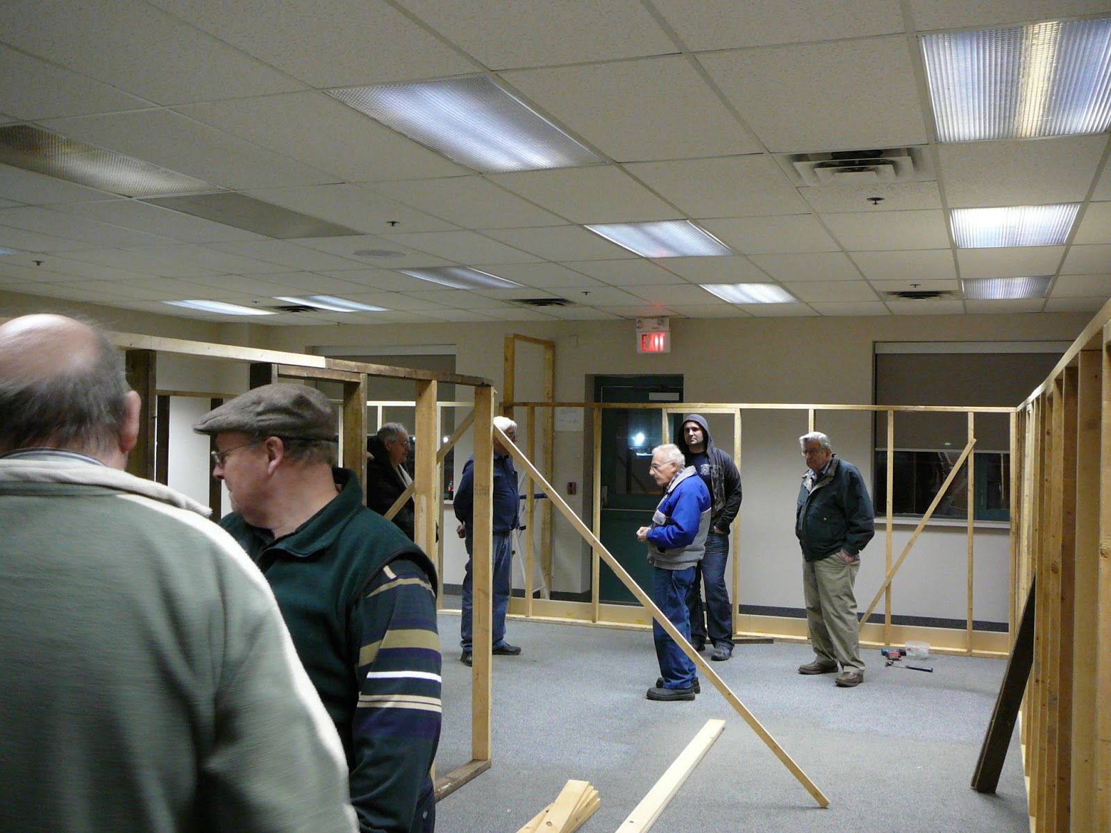
Don and Jim secure a door frame as Doug, Ron, Matt and Tom look on. |
Don is no stranger to designing a model railroad, having a few under his belt already. His own layout, The Ontario Western, has all the basic ideas we wanted in our plan. So it was not much of a surprise when he stepped up and unveiled his idea for the foot print of our new layout. Thanks Don, now let's start building. Don's table plan allows the operator to follow their train as it traverses the layout, a highly desired concept. It also allowed us to put a wall aroung the layout, with a door at each end, thus securing the space, just another benefit of a great plan. The plan incorporated a table width of about thirty inches (OK we forgot about the width of the two by four walls) for all of the layout except the main city and the branch line, which are two feet.
 |
| The walls are up. |
Woodstock Model Railroad Club
 A group of model railroad enthusiasts in Woodstock, has set out to build a model rairoad layout set in the fifties and sixties. For the first few weeks, Doug McLean hosted meetings to set the ground work for the club. One of the many hurdles was to set a meeting time that would suit the most members, not an easy task. Tuesday nights from seven to nine was chosen. A large space was rented, and the task of designing a layout began. Many ideas were floated before Don Pearce proposed a table arrangement that fit the space. With a few tweaks it was finalized, wide aisles, long runs of main line, sweeping thirty inch radius curves and no duck unders. We now had a bench work plan, but wait, what would be the table height, the ruling grade, turn out size, roadbed type, balast type, a name, oh so much more to do, but isn't that the fun? Come along as together we build an empire.
Subscribe to:
Posts (Atom)